General Use Strain Gauge F series GOBLET

F series GOBLET general use strain gaugegoblet_log_s CE_logo

These are CE marked strain gauges originated from general use strain gauge F series. They are compliant with RoHS 2 Directive 2011/65/EU and supplied with CE marking. These strain gauges are available as GOBLET besides the conventional F series gauges which are the most commonly used strain gauges in our product line. The backing of this strain gauge is color coded for identification of the material for self-temperature-compensation. Extension leadwires are also available with CE marking.

General Use Strain Gauge F series GOBLET
Applicable specimen Metal, Ceramics, Composite
Operational temperature -196 to +150 ℃
Temperature compensation range +10 to +100 ℃
Applicable adhesive CN, P-2, EB-2
Backing Special plastics
Element Cu-Ni alloy foil
Strain limit 5 % (50000 x 10-6 strain)
Fatigue life at room temperature 1 x 10⁶ (±1500 x 10-6 strain)
  • For general measurement  Single-element / two-element / three-element

    Single-element (G.F. 2.1 approx.)

    Gauge pattern Type

    Gauge
    length
    (mm)

    Gauge
    width
    (mm)

    Backing
    length
    (mm)

    Backing
    width
    (mm)

    Resistance (Ω)
    flgb_111 FLGB-02-11
    FLGB-02-17
    FLGB-02-23
    0.2 1.4 3.5 2.5 120
    FLGB-1-11
    FLGB-1-17
    FLGB-1-23
    1 1.1 6 2.5 120
    flab_311 FLAB-03-11
    FLAB-03-17
    FLAB-03-23
    0.3 1.4 3 2 120
    FLAB-05-11
    FLAB-05-17
    FLAB-05-23
    0.5 1.2 4.3 2.2 120
    FLAB-1-11
    FLAB-1-17
    FLAB-1-23
    1 1.3 5 2.5 120
    FLAB-1-350-11
    FLAB-1-350-17
    FLAB-1-350-23
    1 1.6 4.5 3 350
    FLAB-1W-350-11
    FLAB-1W-350-17
    FLAB-1W-350-23
    1 2 4.7 3.6 350
    FLAB-2-11
    FLAB-2-17
    FLAB-2-23
    2 1.5 6.5 3 120
    FLAB-2-350-11
    FLAB-2-350-17
    FLAB-2-350-23
    2 1.9 6 3.5 350
    FLAB-3-11
    FLAB-3-17
    FLAB-3-23
    3 1.7 7.7 3.5 120
    FLAB-3-60-11
    FLAB-3-60-17
    FLAB-3-60-23
    3 1.2 7.7 3 60
    FLAB-3-350-11
    FLAB-3-350-17
    FLAB-3-350-23
    3 1.6 7.2 3 350
    FLAB-3W-350-11
    FLAB-3W-350-17
    FLAB-3W-350-23
    3 3.2 8.5 5 350
    FLAB-5-11
    FLAB-5-17
    FLAB-5-23
    5 1.5 10 3 120
    FLAB-5-350-11
    FLAB-5-350-17
    FLAB-5-350-23
    5 1.8 9.4 3.8 350
    FLAB-6-11
    FLAB-6-17
    FLAB-6-23
    6 2.2 11 4.3 120
    FLAB-6-1000-11
    FLAB-6-1000-17
    FLAB-6-1000-23
    6 4.6 11 7 1000
    FLAB-10-11
    FLAB-10-17
    FLAB-10-23
    10 2.5 15.4 5 120
    FLAB-30-11
    FLAB-30-17
    FLAB-30-23
    30 2 35 5 120
    flkb_611 FLKB-1-11
    FLKB-1-17
    FLKB-1-23
    1 0.7 4.5 1.4 120
    FLKB-2-11
    FLKB-2-17
    FLKB-2-23
    2 0.9 5.5 1.5 120
    FLKB-6-11
    FLKB-6-17
    FLKB-6-23
    6 1 11 2.2 120
    FLKB-10-11
    FLKB-10-17
    FLKB-10-23
    10 1.6 15 3.8 120

    Each package contains 10 strain gauges.


    2-element 0°/90° Stacked type (G.F. 2.1 approx.)

    Gauge pattern Type

    Gauge
    length
    (mm)

    Gauge
    width
    (mm)

    Backing
    length
    (mm)

    Backing
    width
    (mm)

    Resistance (Ω)
    fcab_211 FCAB-1-11
    FCAB-1-17
    FCAB-1-23
    1 0.7 Φ4.5 120
    FCAB-1-350-11
    FCAB-1-350-17
    FCAB-1-350-23
    1 1.6 Φ8 350
    FCAB-2-11
    FCAB-2-17
    FCAB-2-23
    2 0.9 Φ7 120
    FCAB-2-350-11
    FCAB-2-350-17
    FCAB-2-350-23
    2 1.9 Φ9.5 350
    FCAB-3-11
    FCAB-3-17
    FCAB-3-23
    3 1.7 Φ11 120
    FCAB-3-350-11
    FCAB-3-350-17
    FCAB-3-350-23
    3 2 Φ10 350
    FCAB-5-11
    FCAB-5-17
    FCAB-5-23
    5 1.9 Φ12 120
    FCAB-5-350-11
    FCAB-5-350-17
    FCAB-5-350-23
    5 1.8 Φ10 350
    FCAB-6-11
    FCAB-6-17
    FCAB-6-23
    6 2.4 Φ14 120
    FCAB-10-11
    FCAB-10-17
    FCAB-10-23
    10 2.5 Φ17 120

    Each package contains 10 strain gauges.


    3-element 0°/45°/90° Stacked type (G.F. 2.1 approx.)

    Gauge pattern Type

    Gauge
    length
    (mm)

    Gauge
    width
    (mm)

    Backing
    length
    (mm)

    Backing
    width
    (mm)

    Resistance (Ω)
    frab_211 FRAB-1-11
    FRAB-1-17
    FRAB-1-23
    1 0.7 Φ4.5 120
    FRAB-1-350-11
    FRAB-1-350-17
    FRAB-1-350-23
    1 1.6 Φ8 350
    FRAB-2-11
    FRAB-2-17
    FRAB-2-23
    2 0.9 Φ7 120
    FRAB-2-350-11
    FRAB-2-350-17
    FRAB-2-350-23
    2 1.9 Φ9.5 350
    FRAB-3-11
    FRAB-3-17
    FRAB-3-23
    3 1.7 Φ11 120
    FRAB-3-350-11
    FRAB-3-350-17
    FRAB-3-350-23
    3 2 Φ10 350
    FRAB-5-11
    FRAB-5-17
    FRAB-5-23
    5 1.9 Φ12 120
    FRAB-5-350-11
    FRAB-5-350-17
    FRAB-5-350-23
    5 1.8 Φ10 350
    FRAB-6-11
    FRAB-6-17
    FRAB-6-23
    6 2.4 Φ14 120
    FRAB-10-11
    FRAB-10-17
    FRAB-10-23
    10 2.5 Φ17 120

    Each package contains 10 strain gauges.

  • Glass/Ceramic materials use

    Gauge pattern Type

    Gauge
    length
    (mm)

    Gauge
    width
    (mm)

    Backing
    length
    (mm)

    Backing
    width
    (mm)

    Resistance (Ω)
    Single-element (G.F. 2.1 approx.)
    flab_58
    FLAB-2-8 2 1.5 6.5 3 120
    FLAB-5-8 5 1.5 10 3 120
    90°2-element Rosette (G.F. 2.1 approx.) Stacked type
    fcab_28
    FCAB-2-8 2 0.9 Φ7 120
    FCAB-5-8 5 1.9 Φ12 120
    45°/90° 3-element Rosette (G.F. 2.1 approx.) Stacked type
    frab_58
    FRAB-2-8 2 0.9 Φ7 120
    FRAB-5-8 5 1.9 Φ12 120

    Each package contains 10 strain gauges.

  • Dedicated integral lead wire recommended for F series

    For general use of GOBLET (qualified for CE marking)

    Application Product name Lead wire code Applicable temperature of leadwire (℃) Example of type name
    General use (without temperature change) Paralleled vinyl LJB-F -20 to +80 FLAB-5-11-3LJB-F
    Paralleled vinyl LJC-F FLAB-5-11-3LJC-F
    General use 3-wire paralleled vinyl LJBT-F -20 to +80 FLAB-5-11-3LJBT-F
    3-wire paralleled vinyl LJCT-F FLAB-5-11-3LJCT-F
    Middle - high temperature 3-wire paralleled vinyl LXT-F -20 to +150 FLAB-5-11-3LXT-F
    1-gauge 4-wire Polypropylene 4-wire paralleled (modular plug attached) LQM-F -20 to +100 FLAB-5-11-3LQM-F

    Only the leadwires using lead-free solder are available for GOBLET strain gauges with CE marking.
    Note that “-F” is appended to the type name of the leadwire using lead-free solder.

  • Standard leadwire integrated strain gauge

    Single-element

    Used leadwire: 0.11 mm2 Total resistance of leadwire per meter: 0.32 Ω

    img_flab_ljb

    Type

    Gauge
    length
    (mm)

    Gauge
    width
    (mm)

    Backing
    length
    (mm)

    Backing
    width
    (mm)

    Resistance
    (Ω)
    Lead wire pre-attached Type name of lead wire preattached
    FLAB-1-11
    FLAB-1-17
    FLAB-1-23
    1 1.3 5 2.5 120 Paralleled 1 m
    Paralleled 3 m
    Paralleled 5 m
    3-wire 3 m
    3-wire 5 m
    -1LJC-F
    -3LJC-F
    -5LJC-F
    -3LJCT-F
    -5LJCT-F
    FLAB-2-11
    FLAB-2-17
    FLAB-2-23
    2 1.5 6.5 3 120 Paralleled 1 m
    Paralleled 3 m
    Paralleled 5 m
    3-wire 3 m
    3-wire 5 m
    -1LJC-F
    -3LJC-F
    -5LJC-F
    -3LJCT-F
    -5LJCT-F
    FLAB-3-11
    FLAB-3-17
    FLAB-3-23
    3 1.7 7.7 3.5 120 Paralleled 1 m
    Paralleled 3 m
    Paralleled 5 m
    3-wire 3 m
    3-wire 5 m
    -1LJC-F
    -3LJC-F
    -5LJC-F
    -3LJCT-F
    -5LJCT-F
    FLAB-5-11
    FLAB-5-17
    FLAB-5-23
    5 1.5 10 3 120 Paralleled 1 m
    Paralleled 3 m
    Paralleled 5 m
    3-wire 3 m
    3-wire 5 m
    -1LJC-F
    -3LJC-F
    -5LJC-F
    -3LJCT-F
    -5LJCT-F
    FLAB-6-11
    FLAB-6-17
    FLAB-6-23
    6 2.2 11 4.3 120 Paralleled 1 m
    Paralleled 3 m
    Paralleled 5 m
    3-wire 3 m
    3-wire 5 m
    -1LJC-F
    -3LJC-F
    -5LJC-F
    -3LJCT-F
    -5LJCT-F

    Minimum order quantity is 10 gauges.


    2-element 0°/90° rosette

    Used leadwire: 0.08 mm2 Total resistance of leadwire per meter: 0.44 Ω

    img_fcab_ljb

    Type

    Gauge
    length
    (mm)

    Gauge
    width
    (mm)

    Backing
    (mm)
    Resistance
    (Ω)
    Lead wire pre-attached Type nameof lead wire preattached
    FCAB-1-11
    FCAB-1-17
    FCAB-1-23
    1 0.7 Φ4.5 120 Paralleled 1 m
    Paralleled 3 m
    Paralleled 5 m
    3-wire 3 m
    3-wire 5 m
    -1LJB-F
    -3LJB-F
    -5LJB-F
    -3LJBT-F
    -5LJBT-F
    FCAB-2-11
    FCAB-2-17
    FCAB-2-23
    2 0.9 Φ7 120 Paralleled 1 m
    Paralleled 3 m
    Paralleled 5 m
    3-wire 3 m
    3-wire 5 m
    -1LJB-F
    -3LJB-F
    -5LJB-F
    -3LJBT-F
    -5LJBT-F
    FCAB-3-11
    FCAB-3-17
    FCAB-3-23
    3 1.7 Φ11 120 Paralleled 1 m
    Paralleled 3 m
    Paralleled 5 m
    3-wire 3 m
    3-wire 5 m
    -1LJB-F
    -3LJB-F
    -5LJB-F
    -3LJBT-F
    -5LJBT-F
    FCAB-5-11
    FCAB-5-17
    FCAB-5-23
    5 1.9 Φ12 120 Paralleled 1 m
    Paralleled 3 m
    Paralleled 5 m
    3-wire 3 m
    3-wire 5 m
    -1LJB-F
    -3LJB-F
    -5LJB-F
    -3LJBT-F
    -5LJBT-F
    FCAB-6-11
    FCAB-6-17
    FCAB-6-23
    6 2.4 Φ14 120 Paralleled 1 m
    Paralleled 3 m
    Paralleled 5 m
    3-wire 3 m
    3-wire 5 m
    -1LJB-F
    -3LJB-F
    -5LJB-F
    -3LJBT-F
    -5LJBT-F
    FCAB-10-11
    FCAB-10-17
    FCAB-10-23
    10 2.5 Φ17 120 Paralleled 1 m
    Paralleled 3 m
    Paralleled 5 m
    3-wire 3 m
    3-wire 5 m
    -1LJB-F
    -3LJB-F
    -5LJB-F
    -3LJBT-F
    -5LJBT-F

    Minimum order quantity is 10 gauges.


    3-element 0°/45°/90° rosette

    Used leadwire: 0.08 mm2 Total resistance of leadwire per meter: 0.44 Ω

    img_frab_ljb

    Type

    Gauge
    length
    (mm)

    Gauge
    width
    (mm)

    Backing
    (mm)
    Resistance
    (Ω)
    Lead wire pre-attached Type name of lead wire preattached
    FRAB-1-11
    FRAB-1-17
    FRAB-1-23
    1 0.7 Φ4.5 120 Paralleled 1 m
    Paralleled 3 m
    Paralleled 5 m
    3-wire 3 m
    3-wire 5 m
    -1LJB-F
    -3LJB-F
    -5LJB-F
    -3LJBT-F
    -5LJBT-F
    FRAB-2-11
    FRAB-2-17
    FRAB-2-23
    2 0.9 Φ7 120 Paralleled 1 m
    Paralleled 3 m
    Paralleled 5 m
    3-wire 3 m
    3-wire 5 m
    -1LJB-F
    -3LJB-F
    -5LJB-F
    -3LJBT-F
    -5LJBT-F
    FRAB-3-11
    FRAB-3-17
    FRAB-3-23
    3 1.7 Φ11 120 Paralleled 1 m
    Paralleled 3 m
    Paralleled 5 m
    3-wire 3 m
    3-wire 5 m
    -1LJB-F
    -3LJB-F
    -5LJB-F
    -3LJBT-F
    -5LJBT-F
    FRAB-5-11
    FRAB-5-17
    FRAB-5-23
    5 1.9 Φ12 120 Paralleled 1 m
    Paralleled 3 m
    Paralleled 5 m
    3-wire 3 m
    3-wire 5 m
    -1LJB-F
    -3LJB-F
    -5LJB-F
    -3LJBT-F
    -5LJBT-F
    FRAB-6-11
    FRAB-6-17
    FRAB-6-23
    6 2.4 Φ14 120 Paralleled 1 m
    Paralleled 3 m
    Paralleled 5 m
    3-wire 3 m
    3-wire 5 m
    -1LJB-F
    -3LJB-F
    -5LJB-F
    -3LJBT-F
    -5LJBT-F
    FRAB-10-11
    FRAB-10-17
    FRAB-10-23
    10 2.5 Φ17 120 Paralleled 1 m
    Paralleled 3 m
    Paralleled 5m
    3-wire 3 m
    3-wire 5 m
    -1LJB-F
    -3LJB-F
    -5LJB-F
    -3LJBT-F
    -5LJBT-F

    Minimum order quantity is 10 gauges.

Concrete Compression Testing Sensor CLL-NA

CLL-NA Compression Load Cell 
500kN to 1MNCE

This is a load cell with a flat loading surface. It is used to conduct strength tests on cylindrical concrete specimens. Guide marks on the loading surface allow cylindrical concrete specimens of different sizes to be easily aligned.

Protection ratings : IP 65 equivalent

CLL-NA Compression Load Cell
Features
  • Convenient guide marks
  • Easy handling
  • Specifications

    Type Applied specimen Capacity Rated output Non-linearity Temperature range
    CLL-500KNA ø10 x 20 cm 500 kN

    1.5 mV/V
     (3000 x 10-6 strain) ±0.5 %

    0.2 %RO -20 to +70 ℃
    CLL-1MNA ø15 x 30 cm 1 MN

Concrete Compression Testing Sensor CM-H

CM-H Compressometer (Destructive) 
20000 x 10-6 strainCE

The CM-10H compressometer is designed to conduct a breaking strength test. It measures the compression strain on a cylindrical concrete specimen (10 cm in diameter x 20 cm in length) made of generally used concrete or high-strength concrete. The high-sensitivity strain gauge is assembled into this compressometer to measure the amount of strain. Both the high-sensitivity strain gauge and a cylindrical concrete specimen are provided with coverings to protect them from damage. A cylindrical concrete specimen can be set in the compressometer quickly and easily. This compressometer allows the strain on a wet concrete specimen, taken out right after underwater curing, to be measured. With this compressometer linked with either the CLL-NA or CLH-MNA load meter, it is also possible to measure the modulus of static elasticity.

CM-H Compressometer (Destructive)
Features
  • Usable till destruction of a specimen
  • Easy to install
  • Possible strain measurement of wet specimen
  • Repeated use
  • Specifications

    Type Applicable specimen Gauge length Capacity
    CM-10H ø10 x 20 cm 100 mm 20000 x 10-6 strain

Concrete Compression Testing Sensor CM

CM Compressometer 
50000 x 10-6 strain to 33000 x 10-6 strainCE

The CM compressometer is designed to conduct a strength test. It measures the axial strain on a cylindrical concrete specimen placed in and secured by screws to the inner chamber of this compressometer. It uses a high-sensitivity strain gauge to measure the amount of strain. By multiplying a measurement by a certain factor, the amount of strain can be calculated as a numerical value. Unlike the case of ordinary strain gauges, this compressometer is simple and easy to operate and can be used repeatedly. However, it cannot be used to conduct breaking tests.

CM Compressometer
Features
  • Easy to install
  • Repeated use
  • Easy drawing of stress- strain curve
  • Specifications

    Type Applicable specimen Gauge length Capacity
    CM-10 ø10 x 20 cm 100 mm 50000 x 10-6 strain
    CM-12 ø12.5 x 25 cm 125 mm 40000 x 10-6 strain
    CM-15 ø15 x 30 cm 150 mm 33000 x 10-6 strain

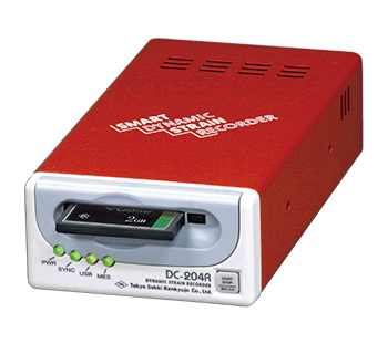
Dynamic Strainmeters Digital type Smart Dynamic Strain Recorder DC-204R/DC-204Ra

Smart Dynamic Strain Recorder DC-204R / DC-204RaCE

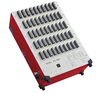
200-kHz high-speed sampling possible in 1-channel mode — connect 8 units at the same time for simultaneous sampling of up to 32 channels.
The DC-204Ra has analog output (±5 V) function for external recorder or automotive ECU.START/STOP button on front allows start of measurement by trigger setting, external trigger, control by external start/stop signal, etc.

Smart Dynamic Strain Recorder DC-204R / DC-204Ra
Features
  • 4-channel configuration with miniature size like postcard
  • 200 kHz sampling (at the fastest in 1-channel mode)
  • Simultaneous 50 kHz sampling for 4 channels
  • Capable of measuring a large strain of up to 80000 x 10-6 strain (with 0.5 V excitation)
  • Data recording in compact flash card of 2 Gbyte capacity
  • Automatic data protection against power failure. When the power is droped unexpectedly, stops measurement and stores data before turning off the power.
  • Data format conforms to DADiSP format
  • External start / stop and external trigger
  • Sensor open-circuit check function
  • USB Interface installed and standard control software supplied
  • Specifications

    Type DC-204R / DC-204Ra
    Measuring object Strain
    DC voltage (with optional CR-4010, CR-4020)
    Thermocouple (with optional TA-01KT)
    Number of channels 4 channels
    Measuring range ±20000 x 10-6 strain (at 2 V excitation)
    ±80000 x 10-6 strain (at 0.5 V excitation)
    Frequency response DC to 10 kHz (-3 dB±1 dB)
    Gauge resistance 120 to 1000 Ω (full bridge)
    Maximum sampling speed 5 μsec (1 ch), 10 μsec (2 ch), 20 μsec (4 ch)
    Analog output
    (DC-204Ra only)
    Voltage output:  ±5 V (5 kΩ load)  ±1 mA
    Output accuracy:  ±0.3 %FS
    Calibration output: ±1 V (added to the input value)
    External dimensions 84(W) x 42(H) x 157(D) mm
    Weight Approx. 500 g
    Power supply DC 10 to 16 V 0.4 A MAX.

Crack Displacement Transducers KG-B

KG-B Crack Displacement Transducer X:-2 to +4 mm Y:±3 mm

The KG-B crack displacement transducer is used to measure the displacement in two directions simultaneously: the displacement of openings, such as concrete cracks or joints, and the horizontal shear displacement. It is mounted on a structure by bonding with adhesive. Because the fixing jigs are detachable, the transducer can be demounted and set on a different structure. This allows this transducer to be used repeatedly on different structures. In addition, the small-size feature makes this transducer suitable for indoor measurement.

KG-B Crack Displacement Transducer
Features
  • Compact, Light-weight
  • Easy to handle
  • Repeated use
  • Specifications

    Type KG-3B
    Capacity X-direction -2 to +4 mm
    Y-direction ±3 mm
    Rated output X-direction Approx. -1 to +2 mV/V (+4000 x 10-6 strain, -2000 x 10-6 strain)
    Y-direction Approx. 1.5 mV/V (3000 x 10-6 strain)
    Non-linearity 1 %RO
    Temperature range 0 to +40 ℃

Crack Displacement Transducers KG-A

KG-A Crack Displacement Transducer
±2 mm/±5 mm CE

This displacement transducer is set across a crack on the surface of concrete or across a joint between two concrete blocks to measure the displacement of surface gaps. Its waterproof structure allows this transducer to make stable measurement outdoors over a long period of time. Mounts using an achor bolt (KGF-11) or mounting brackets (KGF-31).
Temperature-integrated model with built-in thermocouple also available.

Protection ratings : IP 65 equivalent

KG-A Crack Displacement Transducer
Features
  • Drip-proof structure
  • Excellent stability over a long period of time
  • High sensitivity, High accuracy
  • Compact, Easy to handle
  • Specifications

    Type Capacity Rated output Non-linearity Temperature range
    KG-2A ±2 mm Approx. 1.5 mV/V (3000 x 10-6 strain) 0.5 %RO -20 to +60 ℃
    KG-5A ±5 mm Approx. 2 mV/V (4000 x 10-6 strain) 1 %RO

    Output polarity

    img-trout-08

    Measurement moves in the plus direction with regard to an increase of the opening.

Reinforcing Bar Meter KSAT-A

KSAT-A Reinforcing Bar Meter 300 N/mm2CE

The KSAT-A are used to measure stress applied to structural reinforcing bars, and are normally welded at both ends to form part of the reinforcement arrangement. And the meters are with built-in temperature sensor, making possible simultaneous measurement of stress and temperature.

Protection ratings : IP 68 equivalent


KSAT-A Reinforcing Bar Meter
Features
  • Temperature measuring function to measure relative temperature
  • Long-term stable measurement
  • Capable of measuring thermal stress
  • Specifications

    Type Capacity Rated output Non-linearity Temperature range
    KSAT-10A 300 N/mm2 Approx. 2.2 mV/V (4400 x 10-6 strain) 1 %RO -20 to +80 ℃
    KSAT-13A
    KSAT-16A
    KSAT-19A
    KSAT-22A
    KSAT-25A
    KSAT-29A
    KSAT-32A