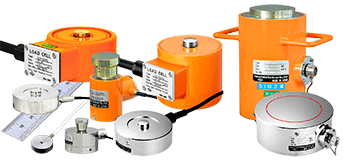
Strain gauge-type transducers electrically convert physical quantities. They operate by converting physical quantities into mechanical stress in a component called a sensing element, and then electrically converting that stress with a strain gauge. The sensing element structure and the strain gauge are optimally designed so as to provide products of superior accuracy and handling. Strain gauge-type transducers are categorized broadly according to their application, into general types and civil engineering/construction types. Some general-type transducers are used in the civil engineering/construction field.
Transducer bridge circuit and connector alignment
Bridge circuit inside and wiring system are given as follows, but not applicable to some products. When connector plug is required, specify it on order to install the plug to the transducer cable.
Rated output and strain value
The output (rated output) of the transducer, one of the most important specifications, is expressed as mV/V. The mV/V is the output voltage when a maximum load is applied to a transducer. It shows the output voltage generated when 1V is applied.
Example:
1.5mV/V means that 1.5mV is output when a load below the transducer's full capacity is applied while 1V is applied to it at the same time. If 2V is applied to it (bridge excitation on a strain measuring instrument):
1.5mV/V × 2V = 3mV
Therefore, if the gauge factor is 2.00 (coefficient set at 1.000) the output voltage of a transducer is 3mV and the value to be shown on a strain measuring instrument can be calculated by the following expression, which is formulated based on the voltage-to-strain relational expression;
 |
⊿e:Output voltage (V) of a transducer(V) E:Excitation voltage(V) K:Gauge factor of a strain measuring instrument ε:Reading on a strain measuring instrument |
With K, E and ⊿e defined as 2.00, 2V, and 3mV, respectively, 3mV is equal to 0.003V and thereforeε = 0.003 = 3000×10-6 strain.
By setting the gauge factor of a strain measuring instrument at 2.00 and taking the output voltage of a transducer for excitation voltage of 1V, we have the following:
2 ⊿e = ε ,then
1mV/V = 2000 x 10-6 strain.
2mV/V = 4000 x 10-6 strain.
Decreased sensitivity due to a long cable used to connect to a transducer
Constant-voltage and constant-current excitation systems are used to provide a strain measuring instrument with the bridge excitation (voltage to be applied to a transducer). If a strain measuring instrument designed for use with the constant-voltage system is used and if a cable (including the attached cable that comes with the transducer unit) must be further lengthened, the sensitivity or the rated output of a transducer deteriorates due to wire resistance. In this case, the rated output (εm) must be adjusted to obtain a new rated output (εs) based on the length and thickness of the longer new cable to be installed by using the following eqauation.
 |
R : Input resistance (Ω) of a transducer r : Total resistance (Ω/m) on the input side per meter of the longer cable L : Length (m) of the longer cable εm : Rated output given on the test data |
Resistance per meter of a cable used to connect to a transdcuer
| Cross section area (mm2) | Total resistance per meter (Ω) |
|---|---|
| 0.03 | 1.15 |
| 0.05 | 0.63 |
| 0.08 | 0.44 |
| 0.09 | 0.40 |
| 0.14 | 0.25 |
| 0.3 | 0.12 |
| 0.35 | 0.11 |
| 0.5 | 0.07 |
| 0.75 | 0.048 |
Transducer cable and wiring
Transducers where the cable end does not have a connector plug are standard, however, an NDIS connector can also be installed. Please indicate beforehand.
Transducer Input/Output resistance
| Input/Output resistance (Ω) |
Pin alignment of connector and resistance between cables (Ω) | |||||
|---|---|---|---|---|---|---|
| A-C RED-BLK |
B-D GRN-WHT |
A-B RED-GRN |
A-D RED-WHT |
B-C GRN-BLK |
C-D BLK-WHT |
|
| 120 | 120 | 120 | 90 | 90 | 90 | 90 |
| 350 | 350 | 350 | 263 | 263 | 263 | 263 |
Not applicable to some products
TEDS sensor support
To read a physical value using a strain gauge type transducer, sensitivity of individual transducer must be set to a strain measuring instrument such as an indicator. While an indicator can accept combination with various transducers, transducer parameters including sensitivity must be set to the indicator every time the combination is changed.
TEDS is an abbreviation of Transducer Electronic Data Sheet. A TEDS transducer has sensor information conforming to IEEE1451.4 as electronic data inside. It enables automatic input of sensor information including sensitivity and serial number into the measurement system by merely connecting the transducer to the system, like as PC plug and play. This automation eliminates wrong settings, significantly reduces the time required for settings and also realizes efficient and simple works. For more information about TEDS transducers and indicator systems, please contact us.
More Information