Junction Box
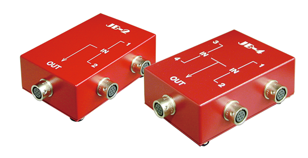
Junction Box JB-2/JB-4
This junction box is used to connect two or four strain gauge type transducers and average the outputs of those transducers. The mean value is easily measured by a digital indicator or data logger.
It can also be used as a branching box to divide the connection of switching boxes into two or four series.
-
Specifications
Type JB-2/JB-4 Number of input points JB-2 : 2
JB-4 : 4Dimensions 80(W) x 50(H) x 120(D)mm Weight Approx. 220g
Examples of use
Example of use as an input averaging junction box

・Strain gauge type transducers to be connected must be of the same capacity, rated output and input/output resistance
・The input/output resistance viewed from the instrument is as follows.
(Input/output resistance of one transducer) divided by (Number of connected transducers).
The calculated value above must be within the range of the instrument specification.
Example of use as a branching box

As the inside of the junction box is wired with 7 wires (for terminals A to G), the junction box can also be used as a branching box as the above. Each connection between the data logger, junction box and switching boxes must be made using an exclusive 7-core cable specified by us.