Dynamic Strainmeters Optional Accessory
Bridge Boxes
The bridge boxes are used for connecting strain gauges in several bridge methods including quarter bridge and half bridge. Fixed resistors for configuring a Wheat stone bridge circuit are inside of the bridge box. For strain gauge based transducers of full bridge configuration, if the transducer is without connector plug on its cable end, it is connected to a dynamic strainmeter using a bridge box by connecting cable wires to the bridge box terminals. The bridge method is determined by the way of connection to the terminals or by the setting of switches depending on the type of bridge box.
-
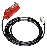
These are compact 1-point bridge boxes. Switch operation allows easy switching to any of these bridge methods: quarter bridge 2-wire, quarter bridge 3-wire, half bridge, and full bridge. A lead wire can be connected by both soldering and screwing on.
Discontinued productType SB-121A/SB-351A Number of channels 1 channel Bridge method Quarter Bridge 3-wire (Quarter Bridge with short-circuit bar)
SB-121A : 120 Ω
SB-351A : 350 ΩHalf Bridge, Full Bridge
60 to 1000 ΩConnection Screwing or soldering Cable ø6 mm, 4-core shielded cable 3 m with NDIS 7-pin plug Dimensions 35(W) x 39(H) x 91(D) mm (except projections / bracket / cable) Weight Approx. 160 g (except bracket / cable / connector) -
Bridge Box SB-122A

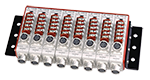
This bridge box can be configured in 2, 4, 6, 8 and 10 channels. The bridge method can easily be chosen among quarter bridge, quarter bridge 3-wire, half bridge and full bridge by the setting of switches.
Type SB-122A-2/4/6/8/10 Number of channels SB-122A-2 : 2 channel
SB-122A-4 : 4 channel
SB-122A-6 : 6 channel
SB-122A-8 : 8 channel
SB-122A-10 : 10 channelBridge method Quarter Bridge 2-wire, Quarter Bridge 3-wire 120 Ω
Half Bridge, Full Bridge 60 to 1000 ΩConnection Screwing or soldering Dimensions SB-122A-2 : 55(W)×35(H)×100(D)mm
SB-122A-4 : 105(W)×35(H)×100(D)mm
SB-122A-6 : 155(W)×35(H)×100(D)mm
SB-122A-8 : 205(W)×35(H)×100(D)mm
SB-122A-10 : 255(W)×35(H)×100(D)mmWeight SB-122A-2 : Approx. 0.4kg
SB-122A-4 : Approx. 0.6kg
SB-122A-6 : Approx. 0.8kg
SB-122A-8 : Approx. 1.0kg
SB-122A-10 : Approx. 1.2kgOption CR-612 attached (the same quantity as the number of channels) -
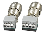
Bridge Box SB-123A/SB-353A

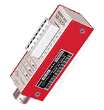
This is a compact universal bridge box employing a clamp-type quick-connecting terminal. Slide switches allow easy switching to any of six bridge methods: quarter bridge 2-wire, quarter bridge 3-wire, half bridge, full bridge, opposite arm half bridge 2-wire, and opposite arm half bridge 3-wire.
Type SB-123A/SB-353A Number of channels 1 channel Bridge method Quarter Bridge, Quarter Bridge 3-wire, Opposite Half Bridge,
Opposite Half Bridge 3-wire
SB-123A : 120 Ω
SB-353A : 350 ΩHalf Bridge, Full Bridge : 60 to 1000 Ω Connecting terminal Clamp type quick connecting terminal Dimensions 30(W) x 30(H) x 90(D) mm (except projecting parts) Weight Approx. 100 g Option CR-612 attached -
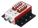
Bridge Box SB-120SB

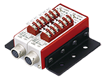
A single SB-120SB bridge box can be used as a relay for a strain gauge type transducer with NDIS connector. Slide switches allow easy switching of bridge method. A lead wire can be connected by both soldering and screwing on.
Number of input points for a single bridge box can be any of five types, from 2 points to 10 points.Type SB-120SB-8/SB-120SB-10 Number of channels 2 channels : SB-120SB-2
4 channels : SB-120SB-4
6 channels : SB-120SB-6
8 channels : SB-120SB-8
10 channels : SB-120SB-10Input Connector Terminal : M3 x 5P terminal
Connectors : NDIS 7P connector receptacleBridge method Quarter Bridge 3-wire (Quarter Bridge with short-circuit bar)
120 ΩHalf Bridge, Full Bridge
60 to 1000 ΩConnection Screwing, soldering or plugging Dimensions SB-120SB-8 : 205(W)×35(H)×100(D)mm
SB-120SB-10 : 255(W)×35(H)×100(D)mmWeight SB-120SB-8 : Approx. 1.2kg
SB-120SB-10 : Approx. 1.4kgOption CR-612 attached (8pcs. for SB-120SB-8, 10pcs. for SB-120SB-10) -
Bridge Box SB-120PY

This is a bridge box capable of measurement in post-yield (large strain) range. Bridge method is chosen by the setting of switches, and measurement range between normal and large strain is also set by a switch. When setting the large strain measurement, sensitivity is decreased to 1/10 of the normal sensitivity. Using a dynamic strainmeter having measurement range of 20000 x 10-6 strain for example, it is possible to measure up to 200000 x 10-6 strain. The large strain measurement is possible in quarter bridge method. The number of channels is available in 2, 4, 6, 8 and 10.
Type SB-120PY-2/4/6/8/10 Number of channels SB-120PY-2 : 2 channel
SB-120PY-4 : 4 channel
SB-120PY-6 : 6 channel
SB-120PY-8 : 8 channel
SB-120PY-10 : 10 channelBridge method
Normal rangeQuarter bridge 2-wire (Quarter bridge with short-circuit between B and C), Quarter bridge 3-wire 120 Ω
Half bridge, Full bridge 60 to 1000 ΩBridge method
Large Strain rangeQuarter bridge 2-wire (Quarter bridge with short-circuit between B and C), Quarter bridge 3-wire 120 Ω Connection Screwing or soldering Dimensions SB-120PY-2: 55(W)×35(H)×100(D)mm
SB-120PY-4: 105(W)×35(H)×100(D)mm
SB-120PY-6: 155(W)×35(H)×100(D)mm
SB-120PY-8: 205(W)×35(H)×100(D)mm
SB-120PY-10: 255(W)×35(H)×100(D)mm
(except projecting parts)Weight SB-120PY-2: 0.4kg
SB-120PY-4: 0.6Kg
SB-120PY-6: 0.8kg
SB-120PY-8: 1.0kg
SB-120PY-10: 1.2kgOption CR-612 attached (the same quantity as the number of channels) -
Bridge Box SB-120B/SB-350B
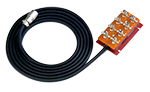
These are used when connecting strain gauges by methods such as quarter bridge 2-wire and half bridge.
They contain resistors for configuring a bridge circuit. Even with full bridge transducers, a bridge box can be used to connect to the terminal where the cable end does not have a connector plug. The bridge configuration is determined by the connection to the terminal.Type SB-120B/SB-350B Number of channels 1 channel Bridge method Quarter Bridge, Quarter Bridge 3-wire, Opposite Half Bridge,
Opposite Half Bridge 3-wire
SB-120B: 120 Ω
SB-350B: 350 ΩHalf Bridge, Full Bridge
60 to 1000 ΩConnection Screwing or soldering Cable ø9 mm, 4-core shielded cable 3 m with NDIS 7-pin plug Dimensions 65(W) x 40(H) x 110(D) mm (except projecting parts) Weight Approx. 0.7 kg -
Bridge Box SB-128A/SB-128A-10/SB-358A
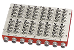
These are bridge boxes of 8-channel and 10-channel configuration.
Type SB-128A/SB-128A-10/SB-358A Number of channels 8 channel (SB-128A/SB-358A)
10 channel (SB-128A-10)Bridge method Quarter Bridge, Quarter Bridge 3-wire, Opposite Half Bridge, Opposite Half Bridge 3-wire
SB-128A/SB-128A-10: 120 Ω
SB-358A: 350 ΩHalf Bridge, Full Bridge
60 to 1000 ΩConnection Screwing or soldering Dimensions SB-128A/SB-358A : 240(W) x 33(H) x 150(D) mm (except projecting parts)
SB-128A-10 : 300(W) x 33(H) x 150(D) mm (except projecting parts)Weight Approx. 2 kg Connection cable CR-612 attached -
SB-120DD-1R/4R/SB-350DD-1R

 This is a bridge box for measuring instruments, compact strain recorder DC-204R, and multi-recorder TMR-321/-323/-221/-223 using a miniplug (PRC07-P8M). Since no cable is required between the instrument and the bridge box, the instrument can be placed compactly. SB-120DD-1R and SB-350DD-1R accommodate quarter bridge 3-wire system (quarter bridge 2-wire accommodates B-B' short) and half bridge methods, and SB-120DD-4R accommodates full bridge method.
When using DC-204R/-204Ra, a CR-6185 sensor cable enables the remote sensing function between an instrument and the bridge box, removing any causes of error from conductor resistance in the cable or ambient temperature change to achieve highly accurate measurement.Number of channels 1 channel Bridge method Quarter bridge 3-wire SB-120DD-1R 120Ω SB-350DD-1R 350Ω Half bridge SB-120DD-1R 120、350Ω SB-350DD-1R 120、350Ω Full bridge SB-120DD-4R 120 ~ 1000Ω Connection Screwing Operational temperature/humidity range 0 to +50℃ 85%RH or less (except condensation) Dimensions 14 (W) × 19 (H) × 59 (D) mm (except projections) Weight Approx. 22 g -
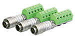
Bridge Box SB-120DG-1R2/1R3/SB-350DG-1R2/1R3/SB-120DG-4R

These are bridge boxes that allow clamp-type quick connection to a measuring instrument. Since no cable is required between the instrument and the bridge box, the instrument can be placed compactly.
SB120DG-1R2 accommodates quarter bridge 2-wire system, and SB120DG-1R3 accommodates quarter bridge 3-wire system.Type SB-120DG-1R2/
SB-350DG-1R2SB-120DG-1R3/
SB-350DG-1R3SB-120DG-4R Bridge method Quarter Bridge
2-wire 120 Ω/350 ΩQuarter Bridge
3-wire 120 Ω/350 ΩFull bridge 120 Ω/350 Ω Number of channels 1 channel Connecting terminal Clamp type quick connecting terminal Dimensions 17(W) x 18(H) x 63(D) mm
(except projecting parts)22(W) x 18(H) x 63(D) mm
(except projecting parts)Weight Approx. 50 g
Carrying Case / Mounting Rack
The carrying case/mounting rack is used for housing DA/DC series dynamic strainmeters to configure a multi-channel measurement system. The case/rack has a power switch, calibration switch and balancing button for operating all channels at the same time.
-
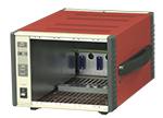
Carrying Case
This case is used to configure DA series or DC series units in multi-channel. A power switch, calibration switch, and balancing button are provided that can be used with all channels at the same time.
Type Number of channels Dimensions (mm) P-4B 4 208(W) x 148(H) x 308(D) (except projecting parts) P-6B 6 288(W) x 148(H) x 308(D) (except projecting parts) P-8B 8 368(W) x 148(H) x 308(D) (except projecting parts) P-10B 10 448(W) x 148(H) x 308(D) (except projecting parts) -
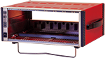
Computer Control Carrying case for DA-17A/DA-37A
This is a case for making a multi-channel system with DA-17A/DA-37A dynamic strainmeters. When the DA-17A or DA-37A units are installed in this case, settings such as low pass filter, balancing, calibration and acquisition of set values and monitor values are available from a computer through LAN interface. A power switch, calibration switch and balancing button are also provided. Carrying cases available for 4-, 6-, 8-, and 10-channel systems.
Type Number of channels Dimensions (mm) P-4AL 4 208(W) x 148(H) x 308(D) (except projecting parts) P-6AL 6 288(W) x 148(H) x 308(D) (except projecting parts) P-8AL 8 368(W) x 148(H) x 308(D) (except projecting parts) P-10AL 10 448(W) x 148(H) x 308(D) (except projecting parts) -
Mounting Rack
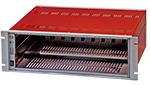
This is a JIS rack to configure a system with up to 10 units of DA or DC series dynamic strainmeters. A power switch, calibration switch, and balancing button are provided that can be used with all channels at the same time.
Type Number of channels Dimensions (mm) R-10B 10 480(W) x 149(H) x 311(D) (except projecting parts) -
Fixing Stand
When a single unit of DA or DC series dynamic strainmeter is used, this stand is attached to the bottom surface of the single unit. It assists to keep the unit upright.
-
One-touch Terminal SB-OT1B
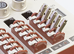
This is a terminal capable of connecting a lead wire by merely pressing down the knob and inserting the lead wire into the hole of the terminal. The lead wire is secured by the spring force of the knob. This terminal is mounted on the input terminal of switching box or bridge box (SB-120SB, SB-121A, SB-351A or SB-122A). One terminal is used for one lead wire, so it is supplied by every 5 terminals.
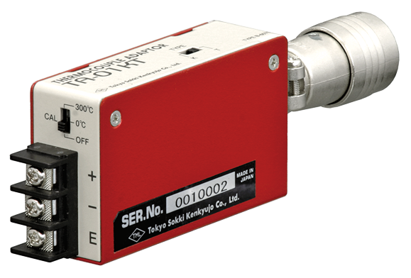
Thermocouple adaptor TA-01KT
This adaptor is intended for temperature measurement by T or K type thermocouple using a DC exciting strainmeter. No external power source is required because the adaptor uses bridge excitation supplied from the strainmeter. It is small-sized and can be directly connected to the connector of a strainmeter, thus saving space for installation.
- Features
- Small and light weight
- External power source is not required
- Built-in reference junction compensation
- Isolation between input and output
- Digital linearization offers excellent linearity
- Burnout detection function provided
- Calibration output for confirmation of strainmeter setting
-
Specifications
Type TA-01KT Number of measurment point 1 Applicable thermocouple K, T Measuring range K : -50 to +1000 ℃
T : -50 to +300 ℃Response time 20 msec or less (0 to 90 %) Measuring apparatus that applies DC exciting dynamic strainmeter
DC-004P
DH-14A
DC-204R/-204Ra
DC-96A/-97A
TMR-300/-200seriesDimensions 22(W) x 41(H) x 70(D) mm (excluding projecting parts) Weight Approx. 100 g Power supply DC 1.95-5.3 V (constant voltage)
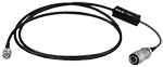
Attenuator cable
Used when measuring voltage with a DC dynamic strainmeter.
-
CR-4010, CR-4020

Cable to connect to the ultra-compact dynamic strain recorder DC-204R and the multi-recorders TMR-321 and TMR-221.
Type Attenuation Length(m) Cable ends CR-4010 1/1000 1.5 BNC Connector
Plug for ultra-compact dynamic strain recorder and multi-recorder (PRC07-P8M)CR-4020 1/100 -
CR-4110, CR-4120
Cable to be connected to dynamic strainmeters DC-004P and DH-14A
Type Attenuation Length (m) Cable ends CR-4110 1/1000 1.5 BNC Connector
NDIS plug (PRC03-12A10-7M)CR-4120 1/100
For multi-recorder
The following options are available for the multi-recorder
-
Multi-Recorder Options
- Multi-Recorder Measurement and Data Processing Software
- Multi-Recorder Measurement and Data Processing Software Visual LOG TMR-7630
Software for multi-channel dynamic measurement and data processing. - Bridge Box SB-120T / SB-350T
- Bridge box for strain 1G/2G/4G units TMR-222/TMR-322.
- Handle TMR-HDL
- Handle for carrying and fixing. (Special screws included)
- Bracket TMR-BKT
- L-fittings for installation. (Special screws included)
- TMR display unit adsorption stand
- A stand with suction cups to fix TMR-381/-281 display units to glass surfaces, etc.
- TMR display unit fixed stand
- This stand secures the TMR-381/-281 display unit to the control unit at any angle.
- Display unit connection cable CR-6442
- Used for extension between TMR-211 and TMR-281 (1.5m)
-
Analytical Method One-dimensional frequency analysis
Maximum and minimum value method, maximum and minimum value method, time method, amplitude method, level crossing method, rainflow methodNumber of Analyse 16 analyses (for 1 ms sampling, arbitrary CH)
80 analyses (for 10 ms sampling, max/min method only)Number of slices Maximum ±50 (100) arbitrary setting
More Information