Monitoring System Controller
Pavement surface Strain Gauge
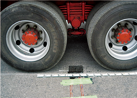
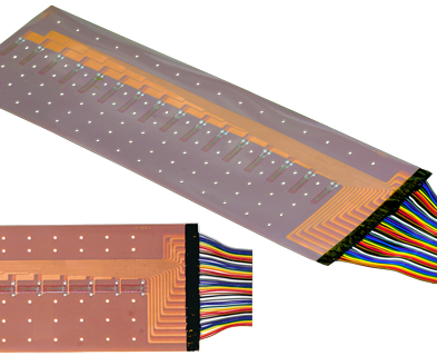
Surface strain distribution gauges for pavement SSM-360-X/-Y
With the goal of measuring strain distribution of paved road surfaces, we developed these gauges jointly with the Civil Aviation Bureau of the Policy Research Institute for Land, Infrastructure, Transport, and Tourism, and with Toa Road Corporation. A gauge can be adhered to a paved surface and accurately measure the strain distribution on the surface layer caused by a wheel load.
| Applicable specimen | Concrete, Asphalt |
|---|---|
| Operational temperature(°C) | -20 to +80°C |
| Operational temperature | +10 to +80℃ |
| Applicable adhesive | PS, RP-2 |
| Backing | Special plastics |
| Element | Cu-Ni |
| Strain limit | - |
| Fatigue life at room temperature | - |
This Pavement surface Strain Gauge is a joint product developed by the Airport Research Department of the National Institute for Land and Infrastructure Management, Ministry of Land, Infrastructure and Transport and Tourism, TOA ROAD CORPORATION and Tokyo Measuring Instruments Laboratory Co., Ltd. (Patented)
-
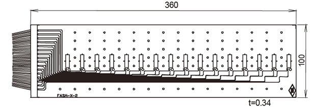
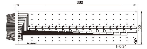
SSM-360-X/SSM-360-Y Details
SSM-360-X
SSM-360-Y
Type Gauge
length
(mm)Gauge
width
(mm)Backing
length
(mm)
Backing
width
(mm)Direction number of elements Resistance
(Ω)SSM-360-X 10 0.9 360 100 X 16 120 SSM-360-Y 10 0.9 360 100 Y 16 120
Socket Wrench Torque Transducer
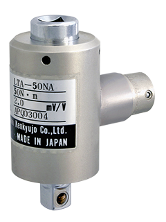
LTA-NA Torque Transducer 50N・m to 500N・m
The LTA-NA Torque Transducer is a high precision transducer that is used to measure tightening force on nuts and bolts. Compact and light weight, it is mounted between the socket and the socket wrench handle. Although the transducer uses a strainmeter to take readings, it can be used to take peak readings simply by connecting it to a peak hold measuring instrument.
Protection ratings : IP 40 equivalent
- Features
- Small, Lightweight
- Easy handling
-
Specifications
Type Capacity Rated output Non-linearity Temperature
rangeLTA-50NA 50N・m 2mV/V
(4000x10-6 strain) ±2%
0.3%RO -10 to +60 ℃ LTA-100NA 100N・m LTA-200NA 200N・m 3mV/V
(6000x10-6 strain) ±2%
LTA-500NA 500N・m 2mV/V
(4000x10-6 strain) ±2%
More Information
Socket Wrench Torque Transducer
Load Cell Accessories
LOAD CELL ACCESSORIES
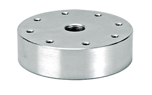
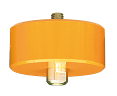
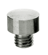
FA SPHERICAL CAP
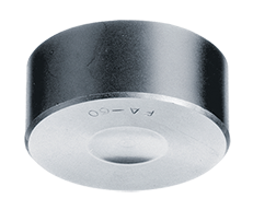
The FA Spherical Cap is mounted to the top of a compression load cell for accurate transmission of compression loads.
| exampleA | exampleB |
|---|---|
 |
 |
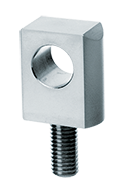
FB-M MOUNTING FLANGE
The FB-M Mounting Flange is used to mount Rod Ends and Eye Bolts to TCLM-NB type load cells.
| exampleC |
|---|
 |
FB MOUNTING FLANGE
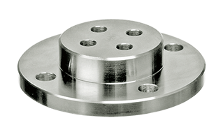
The FB Mounting Flange is used when the mounting area for a compression load cell is unstable or when load cells can not be secured from the bottom.
| exampleD |
|---|
 |
FC SLIDE SUPPORT
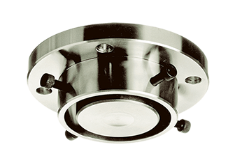
The FC Slide Support can be used to eliminate lateral loads from compression load cells for high precision measurements.
| exampleD |
|---|
 |
FD ROTARY ATTACHMENT
The FD Rotary Attachment ensures smooth load transmission by eliminating torsion during tension load measurements.
| exampleE |
|---|
 |
FE ROD END
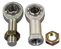
The FE Rod End is ideal when a tension/compression universal load cell is used to measure tension loads on machinery and structures.
| exampleC | exampleE |
|---|---|
 |
 |
FF EYE BOLT
The FF Eye Bolt is used when tension/compression universal load cells are used to measure tension. It can be used with FH Shackle.
| exampleF |
|---|
 |
FG LOAD BUTTON
The FG Load Button is used when tension/compression universal load cells are used to measure compression.
| exampleB |
|---|
 |
FH SHACKLE
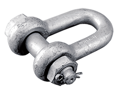
The FH Shackle is used with tension load cells in instances such as measuring wire tension.
| exampleF |
|---|
 |
More Information
Transducer Related Product
Monitoring System Controller
Network Measurement System
Monitoring System Controller MD-111
The monitoring system makes flexible use of TML-NET measurement system. The system consists of controller, network modules and TML-NET compatible transducers. The controller MD-111 controls the network modules and the transducers at specified intervals and stores measurement data in SD card. It is suitable for installation in an instrument storage box or cabinet, and is equipped with input/output contacts. Accordingly, it is most suited for making a measurement system of small scale.

- Features
- Automatic measurement by sleep interval function
- Driven by DC power source
- Small, light and available for installation on DIN rail
- Number of measurement point can be extended easily
- Measurement data are stored in SD card
- Alarm via contact output
-
Specifications
Type MD-111 Maximum number of connection Low-comsumption module 100 modules Conventional module 20 modules(Connection distance up to 150 m) Maximum extension distance Low-comsumption module 1km or less Conventional module 1km or less (for 10 modules or less) Connecting cable Exclusive 2-core shielded cable 2-1.25L1 Number of measurement point 100 points Function Interval measurement, Monitoring Measurement mode Simple measure mode Function of TML-NETset-up Channnel number setting of network module
(Available when connecting only one module)Interval timer 1, 2, 5, 10, 15, 20, 30 minutes, 1, 2, 3, 4, 6, 12, 24 hours
(The starting time of measurement can be specified)Memory card SD memory card (TML specified) Contact input One point: Non-voltage contact, Open collector signal Contact output One point: Relative value, Upper/lower limit value Dimensions 95(W) x 30(H) x 100(D)mm Weight Approx. 200g Power supply DC4.2 to 6.8V
DC9 to 18V
System Block Diagram

More Information
Cantilever type Displacement Transducer
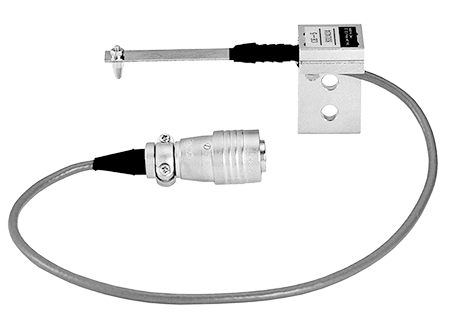
CE Cantilever type Displacement Transducer 2mm to 10mm
The CE displacement transducer has the structure of strain gauges mounted on a cantilever. The high responsiveness to displacement and the simple structure allow this transducer to make accurate and stable measurement and to be installed in a confined space.
- Features
- High Response
- Excellent Stability
- Easy handling
-
Specifications
Type Capacity Rated output Sensitivity
(x10-6strain/mm)Non-linearity Temperature range CE-2 2mm Approx. 2.5mV/V
(5000x10-6strain)Approx. 2500 1%RO 0 to +40℃ CE-5 5mm Approx. 1000 CE-10 10mm Approx. 500 Output polarity

Measurement moves in the minus direction when the contact tip is pushed inward.
More Information
Low Capacity 3-component Load Cell
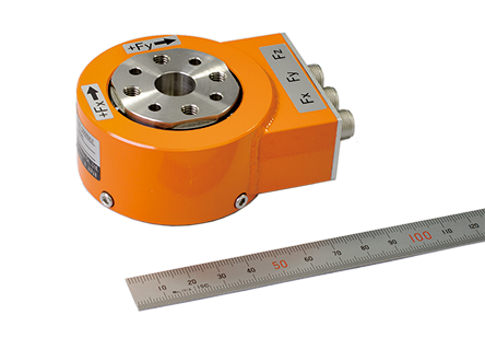
Low capacity 3-component load cell SLP-NA-T 100N to 1kN
The SLP-NA-T is a strain gauge based load cell for simultaneous measurement of forces in three mutually perpendicular axes. Since the load cell is constructed small and light, it is well suited to use in model testing.
Protection ratings : IP 65 equivalent
- Features
- Small and light
- Good response
- Easy handling
- Applicable to wind tunnel testing and vibration testing of models
-
Specifications
Type Capacity Rated output Non-linearity Temperature
rangeSLP-100NA-T 100N 0.5mV/V
(Approx. 2000×10-6 strain)0.5%RO -20 to +80 ℃
(no icing)SLP-200NA-T 200N SLP-500NA-T 500N SLP-1KNA-T 1kN
More Information