High Endurance Strain Gauge
DSF series High Endurance Strain Gauge
These gauges are designed for fatigue tests, and can reach a fatigue life of over 10 million times at a strain level of ±3000 με. Compared to previously (1 million times at ±1500με), these are gauges of exceptionally high durability.
In aviation and other areas, repeated load tests of large elongation of composite materials are conducted. However, it had been necessary to adhere a new strain gauge frequently as a gauge reached its fatigue life. The DSF series greatly reduces time and cost of adhering gauges.
| Applicable specimen | Metal, Composite materials |
|---|---|
| Operational temperature(°C) | -60 to +200°C |
| Temperature compensation range(°C) | - |
| Applicable adhesive | CN, EB-2B, C-1 |
| Backing | Polyimide |
| Element | Special alloy |
| Strain limit | 1% (10000×10-6 strain) |
| Fatigue life at room temperature | 1×10⁷ (±3000×10-6 strain) |
* Because this strain gauge is not self-temperature-compensated, it is recommended to preliminarily measure thermal output of this strain gauge using a dummy specimen which is made of the same material as the test specimen.
-
High Endurance Strain Gauge

Gauge pattern Type Gauge
length
(mm)Gauge
width
(mm)Backing
length
(mm)Backing
width
(mm)Resistance
(Ω)Gauge factor 
DSFLA-2-350 2 2 8 3.3 350 Approx. 3.5 DSFLA-5-350 5 2 11 3.2 350 Approx. 3.5 -
Lead wires recommended for DSF series strain gauges (made-to-order)
Purpose Lead wires Lead wire symbol Operating temperature range
(℃ )Gauge type exampled General measurement (no temperature change) 2-wire parallel vinyl wire LJC -20 to +80 DSFLA-2-350-3LJC General measurement 3-wire parallel vinyl wire LJCT -20 to +80 DSFLA-2-350-3LJCT Medium/high temperature 3-wire parallel special vinyl wire LXT -20 to +150 DSFLA-2-350-3LXT 3-strand twisted FEP single-core wire 6FB♦LT -269 to +200 DSFLA-2-350-6FB3LT * “♦” indicates lead wire length
More Information
High Endurance Strain Gauge
Thunder proof for TML-NET
Magnetic field strain gauge
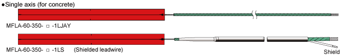
MF series Magnetic field strain gauge
These non-inductive strain gauges are designed for strain measurement in magnetic fields. Two strain gauge elements are overlapped to cancel out electromagnetic induced noise occurring in the gauge, and the twisted lead wire also similarly works to cancel out induced noise. Their structure makes them less sensitive to induced noise from alternating fields.
| Applicable specimen | Metal, Concrete |
|---|---|
| Operational temperature(℃) | MFLA:-20 to +80℃ |
| Temperature compensation range(℃) | - |
| Applicable adhesive | CN, CN-E, RP-2 |
| Backing | MFLA:Special plastic |
| Element | Ni-Cr |
| Strain limit | 1% (10000 x 10-6 strain) |
| Fatigue life at room temperature | 1 x 10⁶ (±1500 x 10-6 strain) |
-
Single-element
Used lead wire 0.08mm2 two-wire twisted vinyl lead wire of 1-m length supplied Lead wire total resistance per meter: 0.44 Ω
Type Gauge length
(mm)Gauge width
(mm)Backing length
(mm)Backing width
(mm)Resistance
(Ω)Lead wire length For concrete
MFLA-60-350-♦-1LJAY60 0.1 64 5 350 Two-wire twisted vinyl wire, 1 m For concrete
MFLA-60-350-♦-1LS60 0.1 64 5 350 Shielded two-wire twisted vinyl wire, 1 m * Orders accepted for 10 units at a time
More Information
Magnetic field strain gauge
TML-NET Compatible Transducers
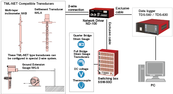
TML-NET Compatible Transducers
This is a strain gauge based transducer with a built-in network module. It is connected to a network driver ND-100, and the ND-100 is connected to a data logger for data transmission. Connection between the transducer and the ND-100 is available using an exclusive two-core cable since the data transmission is made in degital form. Additional TML-NET compatible transducers can be cascaded using the two-core cable.
- Features
- Built-in digital conversion module for TML-NET
- Not influenced by lowering of insulation resistance and no sensitivity decrease
- Easy wiring
- Insulation check feature
System Block Diagram
More Information
TML-NET Compatible Transducers
Low elastic strain gauge
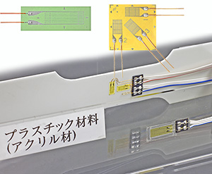
GF series Low elastic strain gauge
These strain gauges are suited for the measurement on materials such as plastics, which have low elastic modulus compared to metals. The specially designed grid pattern reduces the stiffening effect of strain gauge on the specimen. This series is available with self-temperature-compensation for materials having coefficient of thermal expansion of 50 or 70 ×10-6 strain/℃.
New series of strain gauges named GOBLET are added to this series. They are compliant with RoHS 2 Directive 2011/65/EU and supplied with CE marking. Even though lead-free solder is used in the GOBLET gauges, they show better performance than conventional strain gauges owing to the adoption of unique gauge pattern. Extension leadwires with CE marking are also available.
| Applicable specimen | Plastics |
|---|---|
| Operational temperature(℃) | GF GF -20 to +80℃ |
| Temperature compensation range(℃) | +10 to +80℃ |
| Applicable adhesive | CN |
| Backing | Special plastics |
| Element | Cu-Ni alloy foil |
| Strain limit | 3% (30000 x 10-6 strain) |
| Fatigue life at room temperature | 1 x 10⁶ (±1500 x 10-6 strain) |
-
LOW ELASTIC MATERIALS - PLASTICS USE GOBLET


Gauge pattern Type Gauge
length
(mm)Gauge
width
(mm)Backing
length
(mm)Backing
width
(mm)Resistance
(Ω)Single-element
(G.F. 2.1 approx.)
GFLAB-3-50
GFLAB-3-703 2.3 9.5 4 120 GFLAB-6-50
GFLAB-6-706 2.5 14 5 120 GFLAB-3-350-50
GFLAB-3-350-703 2.9 9.5 5 350 GFLAB-6-350-50
GFLAB-6-350-706 2.7 14 5 350 90°2-element Rosette
Plane type
(G.F. 2.1 approx.)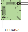
GFCAB-3-50
GFCAB-3-703 1.4 10.5 10.5 120 GFCAB-3-350-50
GFCAB-3-350-703 2.9 14.5 14.5 350 45°/90°3-element Rosette
Plane type
(G.F. 2.1 approx.)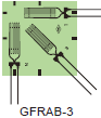
GFRAB-3-50
GFRAB-3-703 1.4 10.5 10.5 120 GFRAB-3-350-50
GFRAB-3-350-703 2.9 14.5 14.5 350 50:Epoxy resin
70:Acrylic resin, ABS resin
Each package contains 10 gauges. -
LOW ELASTIC MATERIALS - PLASTICS USE
Gauge pattern Type Gauge
length
(mm)Gauge
width
(mm)Backing
length
(mm)Backing
width
(mm)Resistance
(Ω)Single-element
(G.F. 2.1 approx.)
GFLA-3-50
GFLA-3-703 2.3 9.5 4 120 GFLA-6-50
GFLA-6-706 2.5 14 5 120 GFLA-3-350-50
GFLA-3-350-703 2.9 10 5 350 GFLA-6-350-50
GFLA-6-350-706 2.7 15 5 350 90°2-element Rosette
Plane type
(G.F. 2.1 approx.)
GFCA-3-50
GFCA-3-703 1.4 10.5 10.5 120 GFCA-3-350-50
GFCA-3-350-703 2.9 15 15 350 45°/90°3-element Rosette
Plane type
(G.F. 2.1 approx.)
GFRA-3-50
GFRA-3-703 1.4 10.5 10.5 120 GFRA-3-350-50
GFRA-3-350-703 2.9 15 15 350 50:Epoxy resin
70:Acrylic resin, ABS resin
Each package contains 10 gauges. -
Leadwire-integrated GF series (made-to-order)
Lead wires recommended for GF series strain gauges
Purpose Lead wires Lead wire symbol Operating temperature range
(℃ )Gauge type exampled General measurement (no temperature change) 2-wire parallel vinyl wire LJC/LJC-F -20 to +80 GFLA-3-50-3LJC General measurement 3-wire parallel vinyl wire LJCT/LJCT-F -20 to +80 GFLA-3-50-3LJCT * Only lead wires using lead-free solder are available for GOBLET series strain gauges with the CE marking.
More Information