Strain Gauges for Transducers
FCT Series
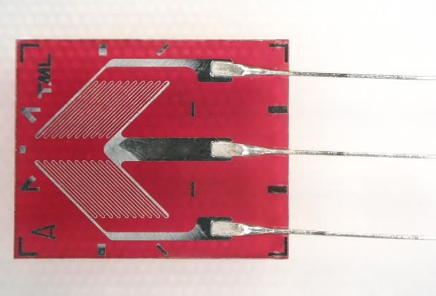
The conventional model, FCT-2-350, featured four gauge leads and was composed of two strain gauges, each arranged at a 45°angle and configured in a quarter-bridge circuit.
The newly added products feature a half-bridge configuration (two-gauge system) with three gauge leads.
This simplifies the bridge wiring and improves work efficiency by reducing the number of lead wires.
While some 45°-oriented strain gauges, such as the FLT-1 series, use a single sensing element, the FCT series employs a design with two strain gauges arranged side by side at 45°, making it easier to integrate into bridge circuits.
By adopting the half-bridge structure, the new design offers greater efficiency and ease of handling.
| Type | Uniaxial, 2-element (for torque measurement) | |
|---|---|---|
| Sensing Element | Material | Cu-Ni Alloy |
| Material | Material | Special Plastic |
| Gauge Leads | Material | Silver-Plated Copper Wire |
| Conductor | 1/0.14 | |
| Round-Trip Resistance per Meter | 2.5Ω | |
| Length | Approx. 25mm | |
| Solder | Lead-Free Solder | |
| Surface Protection | Polyester Film | |
| Creep Code |
A, C, E, G, I, K, M, O, Q, S, U, W |
|
| Measurement Target Materials | 11: Mild Steel 17: Stainless Steel 23: Aluminum |
|
| Operating Temperature Range | -30 to +150℃ | |
| Temperature Compensation Range | +10 to +100℃ | |
| Recommended Allowable Current | 30 mA or less (for metallic measurement target materials) | |
| Strain Limit*1 | 5%(50000με) | |
| Fatigue Life*2 | 1×10⁶ cycles | |
*1 Strain limit is based on results at room temperature
*2 Fatigue life is based on results at room temperature with a strain level of ±1500 με (15 Hz)
-
Single-element
Single-element
Gauge pattern Type Gauge length
(mm)Gauge width
(mm)Backing length
(mm)Backing width
(mm)Resistance
(Ω)
FCT-2-350-A-11-F
FCT-2-350-A-17-F
FCT-2-350-A-23-F2 1.5 7 5.6 350
Creep Compensation
Stable and high-precision creep characteristics are essential for strain gauge-type transducers. Generally, creep compensation is achieved by offsetting the creep of the elastic body (positive) and the creep of the strain gauge (negative). Our product allows for high-precision creep compensation by finely categorizing the turntab dimensions and identifying them with a creep code.
| Gauge creep |
|
|
|---|---|---|
| Creep code | New Product |
|
| Existing Product |
|
|
Features
- Torque strain gauge for transducers with creep code
- Half-bridge configuration
- Gauge leads oriented in the same direction for easier terminal wiring
- Gauge length: 2 mm
- Gauge resistance: 350 Ω
- 12 creep code patterns available: A, C, E, G, I, K, M, O, Q, S, U, W
- Lead-free solder specification (CE compliant)
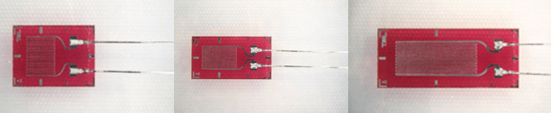
FLAB Series
Our finely tuned creep compensation enables shorter development times for high-precision transducers, making it easier to achieve superior performance with strain gauge-based designs.
The FLAB series supports temperature compensation for materials with thermal expansion coefficients of 11, 17, and 23 ppm/℃. It also allows accurate strain measurement as a direct replacement for conventional creep codes C2, C4, C6, and C8.
| Type | Single-element | |
|---|---|---|
| Sensing Element | Material | Cu-Ni Alloy |
| Gauge Base | Material | Special Plastic |
| Gauge Leads | Material | Silver-Plated Copper Wire |
| Conductor | 1/0.14 | |
| Round-Trip Resistance per Meter | 2.5Ω | |
| Length | Approx. 25mm | |
| Solder | Lead-Free Solder | |
| Surface Protection | Polyester Film | |
| Creep Code |
A, C, E, G, I, K, M, O, Q, S, U, W |
|
| Measurement Target Materials | 11: Mild Steel 17: Stainless Steel 23: Aluminum |
|
| Operating Temperature Range | -30 to +150℃ | |
| Temperature Compensation Range | +10 to +100℃ | |
| Recommended Allowable Current | 30 mA or less (for metallic measurement target materials) | |
| Strain Limit*1 | 5%(50000με) | |
| Fatigue Life*2 | 1 × 10⁶ cycles | |
*1 Strain limit is based on results at room temperature
*2 Fatigue life is based on results at room temperature with a strain level of ±1500 με (15 Hz)
-
Single-element
単軸
Gauge pattern Type Gauge length
(mm)Gauge width
(mm)Backing length
(mm)Backing width
(mm)Resistance
(Ω)
FLAB-2-350-A-11
FLAB-2-350-A-17
FLAB-2-350-A-232 2.9 6 4.5 350 FLAB-3-350-A-11
FLAB-3-350-A-17
FLAB-3-350-A-233 2 7 3.8 350 FLAB-6-350-A-11
FLAB-6-350-A-17
FLAB-6-350-A-236 2.6 10.6 4.5 350
Creep Compensation
Stable and high-precision creep characteristics are essential for strain gauge-type transducers. Generally, creep compensation is achieved by offsetting the creep of the elastic body (positive) and the creep of the strain gauge (negative). Our product allows for high-precision creep compensation by finely categorizing the turntab dimensions and identifying them with a creep code.
| Gauge creep | Large → Small | |
|---|---|---|
| Creep code | A > C > E > G > I > K > M > O > Q > S > U > W | |
Features
- Uniaxial strain gauges for transducers with creep codes
- Gauge lengths: 2 mm, 3 mm, and 6 mm
- Gauge resistance: 350 Ω
- 12 creep code patterns available (A, C, E, G, I, K, M, O, Q, S, U, W)
- Lead-free solder specification (CE compliant)
More Information